SFAX User Guide
| Table of Contents | |
|---|---|
| Overview | basic terminology and how things work |
| Program Menus | description of top level menu options |
| Getting Started | how to setup a user configuration |
| MySetup View | where equipment is selected and setup |
| Spine Match View | find the perfect arrow |
| Sight Tape View | format and print sight tapes |
| Mark Chart View | format and print mark charts |
| Cut Chart View | format and print cut charts |
| Simulation View | see where your arrows impact |
| Ballistic View | display equipment performance |
| Calibration View | calibrate program settings |
| Diopter | determine actual diopter |
| Wizard | quickly build a new user record |
| Find It | search databases for something |
| Journal | document you results |
| Stickbow Setup Tips | configuring non-compound bows |
| MM+CC VS MM+D | counting click versus dial numbers |
| Setting Peep Height | best peep height for a shooting event |
| Velocity From Marks | calculate velocity from shot in marks |
| How To Make A Tape | what to do after you print a sight tape |
Overview
What follows is an explanation of the terminology and language used to describe OnTarget2! (OT2) Software For Archers Xpert (SFAX) program functionality. The item in bold is the name of the feature or convention, and the explaination or definition following.
Screen: the work area of the application currently visible.
Toolbar: a row of icons below the program's main menu that have menu functionality exposed for quick, single click access.
Navigate Buttons: along the left side of the screen or view andbelow the Toolbar. Clicking a Navigate Button loads the associated viewand work area.
Frame: an area of a view that is contained in a rectangular box, usually with a descriptive header at the upper left corner.
Sub-Tabs: divide a view into workable smaller related units. Sub-Tabs are usually placed in the middle of a viewable area.
Radio Buttons: groups of two or more related program options, only one of which can be active at a given time; the buttons are tiny, white circles with the selected option having a black dot in the middle.
Check Boxes: program options, of which one or more, none, or all may be "selected"; the check boxes are tiny boxes, when selected they have a"check mark" in them.
Buttons: cause the program to execute some function or operation. They usually have a descriptive wording or symbol on their face to denote their function.
Push Button: a button with an "<" sign, usually next to a locked edit field containing database information, that when clicked causes the program to "push" that specific data to the edit field to the left.
Edit Field: a white box that accepts user input in the form of numbers or letters.
LockedEdit Field: a field about the size of an edit field, but light green in color. Light green means you may not edit. Some locked edit fields can be changed to a regular edit field by clicking an associated radio button. Other locked edit fields are permanent; the program puts data in them and the user is not allowed to change it.
Calculation Field: afield about the size of an edit field, but light blue in color; the color makes the field easily discernable from other field types. Light blue means that the program does a calculation or loads data for you. You may not edit a calculation field.
Spinner: a group of two buttons, one with an "up arrow" and one with a "down arrow" on their face. They are usually located next to an edit field and, when clicked, change the edit field value a predetermined amount up or down.
Combo Box(or List Box): looks like an edit field with a down arrow button on the rightside. Clicking on the down arrow allows selection of an item contained in a drop down list.
Slider: a control that allows the user to click on the associated pointer and drag left/right or up/down, to quickly change a program value.
Data Sheet: a chart or grid that displays associated program values, data, or records.
Scroll Bar: attached to the right side (or bottom) of a data sheet; It has a square button that the user can click and drag to cause the attached data sheet to scroll or expose new data.
Dialog and Message Box: something the program loads and displays as a result of user input or a program error.
Getting Started
Pretty simple really. Visit the MySetup View. Select the Databases sub-tab. Find your equipment in the databases; remembering to click each "Apply" button after making your selections. Certain data like draw weight and draw length are not sent to the Bow Specs sub-tab. The assumption is that these values have already been set and you don't want them changed when switching to a new bow. The locked edit fields are informational. The Databases sub-tab sole purpose is extracting info from the databases. All selections you make on the Databases sub-tab are not saved or remembered when you shut down the program. After you've made your choices, visit the configuration sub-tab for Bow Specs, Arrow Specs, and Sight Specs; fine tuning and customizing each as required. Once you've gotten to the point that you would not want to re-type or start over, save your information in a user record. Select File on the main menu, then select Save User Record. Your saved user record can now be restored any time you need it. You're now ready to visit the other views and start playing the various program features. Click a Navigate Button and you'll have a new program view. Some views also have sub-tabs located at their centers. Click the sub-tabs, too.
Every effort has been made to include accurate specs for the equipment databases. It's possible that your bow's dimensions might not exactly match what's in the database. If so, get out the tape measure and record the real dimensions. Enter the changes where necessary. Remember the computer acronym GIGO (garbage in garbage out) when taking measurements, as the program can only be as accurate as the data you feed it
Possibly the two most important measurements you'll need to record for the purposes of making sight tapes are Peep Height and Sight Radius. These two measurements are key to obtaining good results when making sight tapes or charts. They should be as accurate as you are capable of measuring. Peep Height is measured from the centerline of the peep to the centerline of the arrow shaft. Sight Radius is measured from the center line of the peep to the plane of the scope lense or pin(s). Both measurements must be taken while at full draw. If you shoot without a peep sight, substitute "your eye" for the peep when taking the measurements. Use "eye to plane of scope lens/pins" and "eye to centerline of shaft".
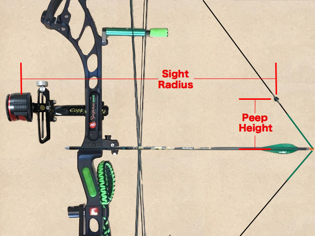
How To Measure
Peep Height and Sight Radius
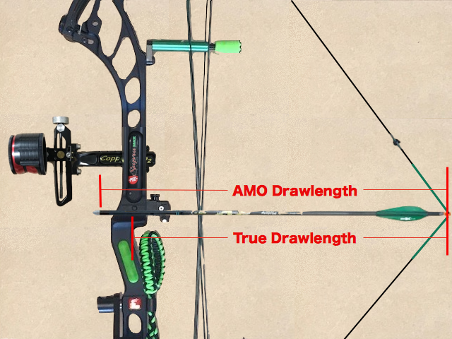
How To Measure
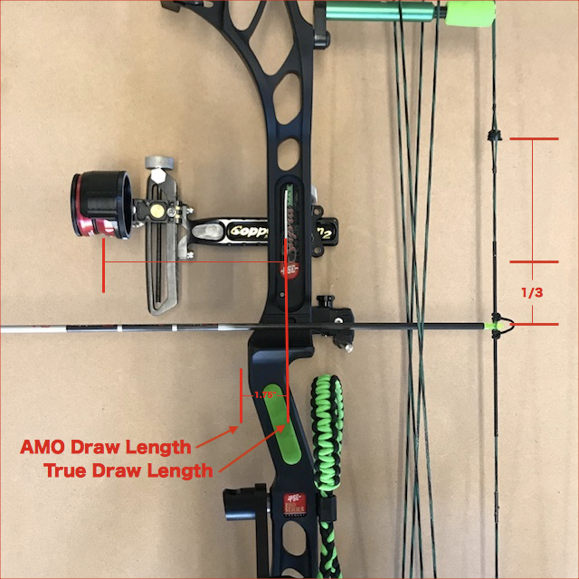
Draw Length
An accurate draw length is required for calculating arrow spine requirements. There are two methods of measuring draw length. True Draw Length is measured from the low point of the grip to the nock groove while at full draw. The low point of the grip is usually in line with the rest attachment hole in the riser. AMO Draw Length is True Draw Length plus 1.75 inches. Manufacturers label bows and cams with the AMO draw length measurement. It is a good idea to actually check your bow's draw length to make sure that the draw length stated by the manufacturer or listed on the cam is accurate. All Pinwheel Software programs use only AMO Draw Length. Some companies consider plus or minus a half an inch for a draw length measurement to be OK, while other manufacturers are spot on. This is mentioned only because a half inch difference between stated and actual AMO draw length will make a difference in both calculated velocities and shaft recommendations the program makes.
After the peep height and sight radius measurements, arrow components are the next most important data you will need. The data you enter about your arrow will provide the app with information to make its drag model. The arrow database is fairly complete with over 1200 shaft types and sizes. Select the shaft, fletching, and nock from the databases and click Apply for each selection. In a future release, you'll be able to supply info on shafts not in the database.
The program will do a good job of estimating the velocity generated by your setup, if you provide accurate data. To get the most accurate tapes and charts, you need an accurate velocity. Velocity calculations are done on the Sight Specs sub-tab. The most accurate method for determining velocity is from your own Sight Scale Marks or known Pin Gaps. For calculating velocity from sight marks, enter two or more sight-in distances and a scale mark for each, and then let the program calculate your velocity. You can use as few as two marks. Using more marks and enabling the "cross check" feature, allows you to double or triple check your mark settings. The velocities calculated by the program should be fairly consistent and not vary by a large amount. A large variance means a possible "bad mark".
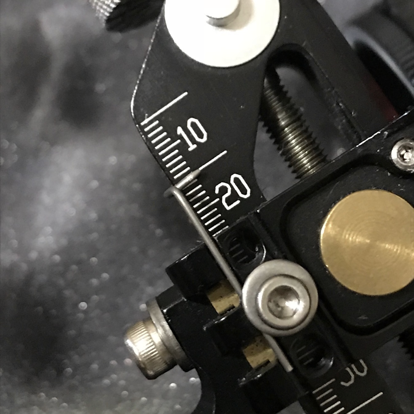
Pin Gaps may also be used to calculate your velocity. The process is similar to calculating from sight marks. The only difference is you need an accurate measuring device, like a micrometer or dial-caliper. Inexpensive micrometers may be purchased at places like Harbor Freight Tools. If you don't have a micrometer or dial-caliper, measure to the nearest 1/64 inch using a fine scale ruler and make a decimal conversion of your measurement. If you use a measurement to the closest 1/64 inch, your marks or calculated velocity will be very close, but not exact.
When entering or modifying data in the edit fields, you might run into the situation that you enter some value and find that th program sets it to something else. This is the program's data validation at work. Each edit field is range checked to insure that you are not entering something that will cause a program error. If you run across a field that you don't think you'll need, leave it at the default setting. Every effort has been made to make the program as bullet-proof as possible in regards to data errors, but don't go zeroing out a field (or inserting " "s) just because you think you don't need it. Once you make all your initial selections and changes, save your user record.
MySetup View
The MySetup view and sub-tabs contain all the information about the currently loaded user record equipment configuration. At program startup, a default user record is loaded. This is by design to insure that the app has valid accurate data to work with when it loads. You can change this behavior by selecting one of the load options from the On Entry main program menu option.
Almost everything required to make the application work can be found in one of the MySetup view sub-tabs. In the event that the user cannot find their equipment in one of the five databases, the weight and dimension data can be manually entered by the user in the appropriate edit field of the MySetup sub-tab.
Most information about equipment dimensions, weights, and performance may be located in archery equipment owner manuals, sales catalogs, or on the manufacturer websites. Navigating from field to field on the MySetup sub-tabs can be accomplished by a press of the tab key or a mouse click with the mouse pointer over a specific edit field.
Making changes to edit fields on the Bow Specs, Arrow Specs, or certain Sight Specs sub-tabs cause the program to do a recalculation, if one is required. When a recalculation is made the values for arrow velocity and/or weight, front of center, grains per pound of draw weight, holding weight, K/E and Momentum will display in the appropriate calculation fields and populate the other program views when they are visited.
The Database Selections sub-tab contains five equipment databases for bows, shafts, sights, fletching, and nocks. When running the program for the first time or when creating a new user record, this sub-tab should be the first place the user visits. If the manufacturer name of the equipment is known, it can be easily located by clicking on and searching through the various combo boxes in choice frames. When selecting a bow model year, the bow manufacturer combo is automatically populated with data for that model year. As the user selects equipment from each of the databases, range spreads (for bows) and exact data information is displayed in no-edit fields directly below the combo boxes. Data that the user might want to modify is placed in edit fields of the Bow, Arrow, or Sight Spec sub-tabs, after the user clicks the Apply button.
If the user notices a discrepancy in what the database displays and what they know to be the true measurement or weight of their equipment, they are free to modify the edit fields after sending the database info to the respective sub-tab. When finished selecting equipment from each equipment database, the user clicks the Apply button (or buttons) as required, to send their choices to the MySetup respective Bow, Arrow or Sight Spec sub-tabs. With the bulk of data selection now complete, the user can click the Bow, Arrow or Sight Spec sub-tabs, and continue to fine tune their selections or just view the results.
For non-compound bows, instead of axle-to-axle, you use the AMO bow length. Most traditional bows will be labeled around the grip area with the AMO length.
On the Database tab of the MySetup screen..bottom middle..there are 3 selection boxes. Recurve and Longbow types are in the top generic bow selection box, that by default displays "Compound". Make your recurve or longbow selection
based on the performance characteristic of your specific bow. For additional setup tips for Recurves and Longbows.
The Bow Specs sub-tab allow the user to fine tune or record weights or measurements for their bow in the currently loaded user record. Frames for Weight On String, Bow, and Measurements are provided for inputting the data. Care should be taken to insure accuracy. Default weights for d-loop, peepsight, and nock point are provided, but the user should make their own measurements whenever possible. Calculation fields show the results of the data input fields.
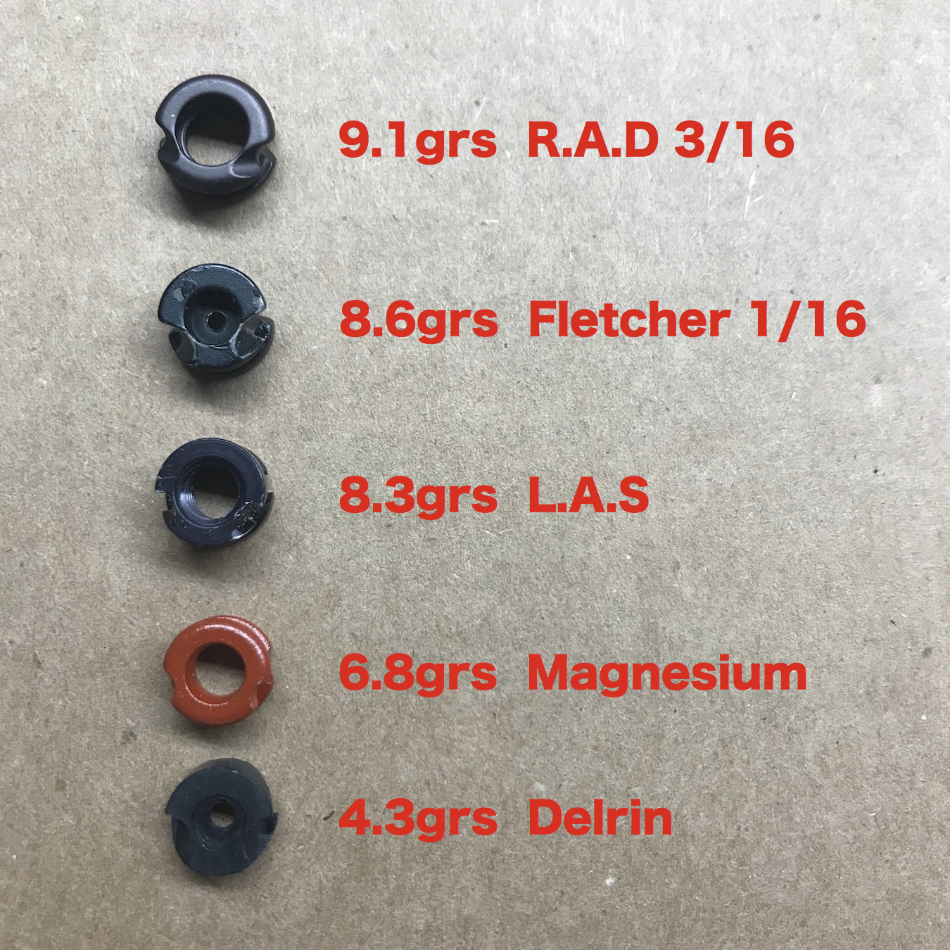
Peep SIght Weights
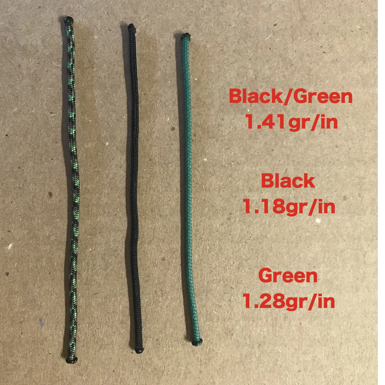
D-Loop Material Weight
Peep weights vary by manufacturer, material used, and peep hole size. Meta Peeps can be from 5-8grs. Peeps with large housings or with clarifier or verifier lenses can weigh from 18 to 28grs, depending on whether just the peep or the peep and lens are used. When in doubt, visit the manufacturer website or use a grain scale to determine actual weight of your components. Note on Silencer DFC; DFC stands for "Distance from Cam". It is measured from the point where the string separates from the cam or idler wheel with the bow at rest. If the string silencers are at different distances from the top and bottom cam/idler, then split the difference; add the two different distances and divide by 2.
The Sight Specs sub-tab allows the user to select the appropriate sight type with a combo box selection or from a sight supplied from the Database Selection sub-tab. Options are Target Sightw/Scope (linear models like SureLoc, Copper John), Linear w/o C;licks, SH (SpotHogg) Dial FE (FastEddie) W/O Clicks,, HHA Dial, HHA KingPin, Slider, Milti-Pin, and NFAA Pin., G5 XR1+1, G5 XR3+1, and None. The Sight Spec sub-view changes depending on the sight type selected. Fields common to all types of sights are Peep Height, Sight Radius, Clicks Per Mark, and Click Value.
As mentioned previously, Peep Height and Sight Radius measurements are critical to creating accurate sight tapes or pin gaps and calculating velocities. If you don't have a helper, an approximate measurement of Peep Height can be made by using your front sight. A detailed discussion can be found here in the Velocity From Marks section.
Pin sights are considered generic and are not found in the program sight database. The reason for this is that all pin sights have a certain number of pins that may be spaced at varying distances at the discretion of the user. There is usually no drive or screw-pitch associated with pin sights. The Pins information is displayed when Multi-Pin Sight is selected from the sight combo box and disappears when one of the other sight options is active. Pin Count, Start Distance, and Pin Spacing are fields the user can modify to fit their specific pin sight. The pin Count can be from 1-8 and default is 5. The Pin Spacing can be from 5-20 and defaults to 10. Start Distance can be from 15-50 and the default is 20. For Pin Sights, use the Clicks Per Mark and Click Value that come from the database or use the program default values.
NFAA Pin is a variation of the standard multi-pin settings. The selection is for those who compete in the NFAA Pin classes. The current limitation for these classes is 5 individual pins. Usually archers competing in the NFAA Pin classes have user specific distances for their 5 pins. This is accommodated in the program by 5 individual pin distance spinners that can be set for distances ranging from 15 to 120. The Default settings for NFAA Pin are 15, 25, 40, 60, and 80. The user can set the five pin distances to whatever they've determined to be their optimal distances.
The Extension Index is informational only. It doesn't matter from which end of the sight extension you count from. It is supplied so the user can note which extension detent is used to attach their sight.
Track Adjust for most sights can be extracted from the sight database. Generally, the track adjust value in the database is accurate, but occasionally the sight manufacturers make design changes that affect the track adjust value. Since sights rely on the Track Adjust to get correct mark spacing on tapes, it's a good idea to double check the value from the database. This is especially true if you have a sight that indicates a track adjust value other than 1.0. For most linear style sights, the track adjust value should be set to 1.0. Copper John and single pin, slider style sights are the exception to this rule. For slider style sights the track adjust ratio is extremely important because the scope head usually moves at a different rate than the tape pointer. You might have to experiment with it for best results.
You can figure out the Track Adjust value yourself if you have access to an accurate measuring device, like a micrometer or dial-caliper using any of three methods.
Method 1
Distance on frame
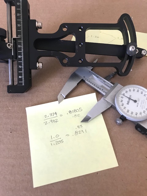
Method 1) Measure the distance between two marks on the sight's tape mounting radius, and measure the distance that the scope head moves when you change from one mark to the other. Example: Two marks on the tape mounting radius are 1.0" apart. When you move from one mark to the other the scope head moves 1.205"....so...1.0 / 1.205 = 0.8291 or rounded to 0.83. The 0.83 would be your Track Adjust.
Method 1
Distance on radius
Method 1
Distance on frame
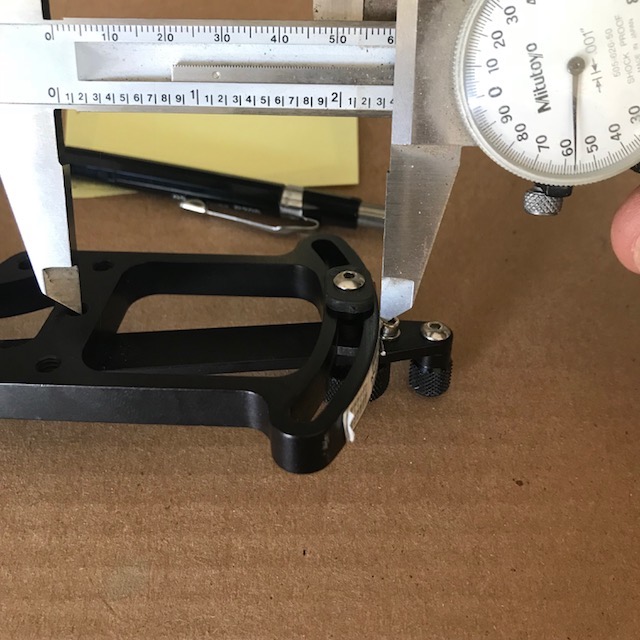
Method 2) Measure the distance between the tape mounting radius and the lever pivot point; call this distance A. Measure between the lever pivot point and the scope head vertical slide or track; call this distance B. For most slider sights, Distance A will usually be larger than distance B; but in the case of the SureLoc pictured, B is larger. Divide A by B...example: DistanceA=2.374, Distance B=2.902. So 2.374/2.902=0.81805 or rounded to 0.82. This should get you close.
Method 2
Distance "A"
Method 2
Distance "B"
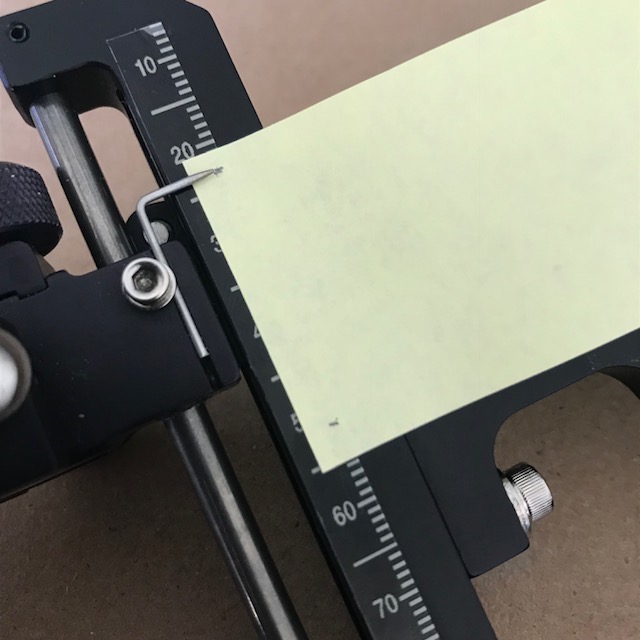
Method 3) If you don't have a way to measure the vertical/curved trackratio, you can do it by "trial and error". Make a tape with marks every 5 yards. Put it on your sight so the 20 on the tape corresponds to your 20 yard pencil mark sight in distance. Use the tape and compare to one of your "penciled" marks on the tape mounting radius area. Say your 50 yard pencil mark corresponds to 55 on the tape. Make changes to the Track Adjust value until the 50 on the tape agrees with your 50 pencil mark. Increasing the Track Adjust value spreads marks further apart. Decreasing the Track Adjust value will cause the marks to move closer together.
There are two methods for calculating a velocity on the Sight Specs sub-tab. The method used is determined by the sight style selected by the user. The velocity is determined from pin gaps or sight scale marks. While the two methods take different inputs they utilize the same general algorithm to arrive at a velocity. Essentially, a pin gap is the same as the difference between two marks on a manufacturer scale. While you need a micrometer to measure a pin gap, the manufacturer scale used in conjunction with the clicks per mark serves the same function with accuracy to the click value of the sight used. For determining velocity from marks or gaps, there is now only one restriction on the distances for the first pin or mark used; that is, that it must be equal to or greater than the setup's High Pin (HP) distance. If you enter something that is less than the HP distance, the program will adjust to that range and issue an error message.
Generally, using two marks or gaps around the mid-point of your planned shooting distances give the best results. If you use three or more marks, a mark that is not perfect will show as a variance in the velocity calculation. More than a couple of FPS difference from other velocity results indicates a possible questionable mark or distance. You can eliminate it from the calculation by unchecking its selection checkbox and recalculating.
For Velocity From Marks, record sight settings from the manufacturer supplied sight scale as a mark+click(s) value. A manufacturer scale has marks that are equally spaced for the length of the scale with numbers usually occurring every 5 or 10 marks. SpotHogg Dial sights have numbers every 4 marks. If you have a blank tape on one side of your sight with "pencil marks" for distances and a manufacturer scale on the other, you can use the pencil marks for you sight in marks. If you don't have sight marks, you'll need to go to the range and get them for at least two distances; three marks are even better. Record a mark+click(s) value for at least two distances. Up to three marks and distances may be used. Distances are in either yards or meters. Make sure to toggle the main menu Units dropdown for SAE/METRIC check mark for the range value you intend to use. There are two columns for entering your sight mark data. The left column is for the range or distance. The right column is for the mark+click value associated with the range. Checking a box tells the program you want to use a Range/Scale Mark pair for the velocity calculation. Unchecking tells the program to ignore the associated pair. Once all your data has been entered, click the Calc button in the Sight Marks or Pin Gaps frame. The program will now "shoot" an arrow based on the configuration data you entered on the MySetup sub-tabs and a match a trajectory to your entered and checked distances and mark+clicks. The more data points you use, the more accurate the calculation can be. The resulting velocity calculations, if more than one, are cross checked and averaged to arrive at your velocity number. (See this more detailed write-up on Velocity From Marks)
For Pin Gap Velocity, measure the distance between the two pins using amicrometer, dial-caliper, or other accurate method. Enter the yardage of the first pin you will use in the Range edit field, the yardage of your second pin in the next Range edit field, and the distance you measured between them in the Gap edit field. Now click the Calc button in the bottom of the calculation frame. Results are displayed in the blue Velocity calculation field next to the Calculate button. Up to three pin distances and two gaps may be used. If two gaps are used, thevelocity will first be calculated between pin 1 distance and pin 2 distance, then between pin 2 distance and pin 3 distance. If X-Check(cross check) is selected, three pins and two gaps must be entered, and the velocity will come from the first and third pins. After calculating and cross checking, if two or more velocities are calculated, the end velocity is an average of the either two or three results values. Again, your results will depend heavily on your accuracy in shooting and measuring.
After the velocity calculation has completed, the program selects the Velocity From Marks Or Gaps in the velocity choice combo box. If you do not want to use the velocity calculated from your marks or gaps, reselect the Velocity From Specs or Manual Velocity options in the same combo box. Other program views will use the velocity you select for their calculations. The first checked range and mark+click value will be used to auto-calibrate the mark reference table.
The Cross Check box allows you to double check marks or pins if you use for the velocity calculation. Check this box if you use three marks or pin distances. It will increase the number of check calculations the program makes from the marks or gaps you input. With three marks selected, the program usually performs two calculations; mark 1 and mark 2 then mark 1 and mark 3. With Cross Check enabled, the program can do three calculations; mark 1 and mark 2, mark 1 and mark 3, then mark 2 and mark 3. The more the program can evaluate for you, the better chance it has to create a good calculation and expose bad marks or pins settings.
The Arrow Specs sub-tab allows the user to configure their arrow. The importance of data entered on here is multi-faceted; it helps to define a drag model for use in trajectory calculations and in making sight tapes, as well as calculating everything arrow related: KE, MO, GPI, FOC, velocity, and dynamic spine. Shaft Length is the measured length of the shaft material only. Shaft Length is the measured length of the shaft material only. Shaft Length is the measured length of the shaft material only. That was not a misprint..it was repeated because of its importance. Do not confuse shaft length with AMO arrow length. AMO arrow length is not used by Pinwheel Software products. If you do use AMO complete arrow length in place of shaft length, you will cause the program to make incorrect calculations. Along with weight/mass related errors injected into the trajectory calculations, using the incorrect shaft length will result in errors in the total arrow weight calculated, the FOC calculated, the velocity calculated, the KE calculated, the momentum calculated, and the spine requirements of your setup.
The weight of shafts in grains per inch comes from the shaft database on the Database Selection sub-tab. Weights listed in the database are from manufacturers published specs. The specifications may change between model years or, in some cases, from batch to batch as shafts are manufactured. Some manufacturers label the shafts or packaging with letter sequences or weight ranges. The Grain Per Inch edit field may be changed to reflect the actual shaft weight in grains per inch. If the SFAX calculated total arrow weight is off by more than three to five grains from what has been measured with a grain scale, this would be a logical first place to look to determine the cause. Check manufacturer websites for current weight information.
Fletching data may also be extracted from the database. Manufacturers provide the data, but variations in production runs can cause differences in weights. Usually the variation between runs is less than 1 grain. Variations in color can also influence the weight of vanes, but usually only minor amounts (~0.1-0.2 grains). The larger the vane the more the color will affect the weight.
Fletch Offset is a key component in calculating the drag of a complete arrow. A default setting of 2.0 is considered normal. For helical, this value may be increased toward the max value of 5.0, as required. The value can have a significant effect on sight marks, especially at longer ranges. Changes to this field can be made if there is a noticeable variance in mid-range marks. If mid-range marks are "hot", increase this value to correct. When calculating a velocity from sight marks or pin gaps on the Sight Specs sub- tab, increasing the offset value will raise the calculated velocity, while decreasing it will have the opposite effect.
Spine Match View
The user selects a shaft from the database for evaluation using one of two methods. The first method is to use the combo boxes in the Current Shaft Choice frame to select the brand, model, and shaft size. The alternate method is to set the filters to use and then click the New Search button. This initiates a database search and allows the program to find a selection of potential matches. After the Show Matching table has been compiled and populated, the user can then use the scroll bar (if visible) to look through all the matching shafts that were returned.
Selecting a shaft from the table is as easy as clicking on a table cell in the shaft Mfg or Model column containing the desired shaft. Shaft information in blue calculation fields pertaining to a specific shaft insert or bushing/pin weight are displayed when a new selection is made. The user may optionally use these values instead of what was imported from the MySetup view. Changing the values would make sense, especially when a different shaft has been selected, as most shafts use unique components of varying weights.
Using Search Filters for finding a correctly spined shaft that meets a specific set of requirements is accomplished by utilizing a unique set of filtering mechanisms to refine the search and help the user locate exactly what they're looking for. The user can expand or reduce the range of interest by selecting and setting the filters located in the Search Filters frame. By enabling a filter with a combo box or check box, the user can find matching shafts to fit their needs. Searches by shaft manufacturer or company are by All Manufacturers, Selected Brand Only (a specific manufacturer), or From A Checked List (user determined list of mfgs). Further filtering is accomplished by Shaft Usage (target, hunting or target, or hunting), Shaft Composition (aluminum, carbon, composite(aluminum/carbon)), Shaft Weight range, Shaft Diameter range, or finished arrow FOC range; or any combination of these options. Additionally, the user can choose to omit shaft models that are no longer manufactured by checking the No Discontinued shafts check box. The more filters that are enabled, the more refined the search becomes. If a search returns few or no matches, the range or filters employed in the search may need to be modified or expanded.
The Show Matching sub-tab contains the results of the database search using the filters selected. When the New Search button is clicked, the shaft database is examined for shafts that match the optimal calculated spine and match all the filters in use. The results are shown in the data sheet along with the number of shafts matching the filters in use. The data sheet results may be sorted by clicking on one of the data sheet column header fields. Sort options are limited to sorting a column in ascending or descending order. Clicking the left mouse button while the pointer is over the Mfg or Model column of a data sheet row with a specific shaft will select and load that shaft for usage with the optimal spine graphic. Clicking the check box in the cs (compare shaft column) of the ShowMatching sub-tab will copy that shaft to the Compare Shafts sub-tab.
The Compare Shafts sub-tab is used to collect all shafts that the user may be interested in on one screen for sorting and evaluation. A print feature is planned in a future release. The selected shafts can be compared "head to head" with other selected shafts for velocity, total arrow weight, and KE. Shafts selected for comparison can be sorted by clicking the left mouse button while the pointer is over the column header the user wants to organize. To examine FOC, GR/LB, or see how an individual shaft matches optimal spine, the user must left click on the Mfg or Model row containing the shaft in order to see the details. Clicking the check box in the "cs" (compare shaft column) of the Compare Shafts sub-tab removes the shaft from the comparison table.
Spine Sensitivity Range is the span covered by the graphic spine evaluator and is determined by the Sensitivity value found in the Search Filter frame. The Sensitivity value defaults to 0.025 and determines the calculated width of the green "good" area of the graphic spine evaluator. The value of each tic mark and is defined as one half of the Sensitivity value in use. The tic mark default is therefore 0.0125. If you change the Sensitivity value, SFAX adjusts the tic mark value accordingly. A smaller number entered for the Sensitivity value shrinks the calculated width of the evaluator's green center section and surrounding tic marks and a larger one expands them. This is not to say that the physical(visual) size of the graphic changes, more that a given spine change will appear less dramatic with a large sensitivity value than with a small one. The Sensitivity range value is used to determine just how close a shaft has to match the setup requirements before it's considered "optimal". The value is entered as a positive number (no sign + or -) and the program uses this value during its match evaluations. At the SFAX default settings, the twelve tic mark range covered bythe spine evaluator represents a total span of 0.150 in dynamic spine. Six tics to the right of center green is 0.075 "stiff" and six tics to the left is 0.075 "weak".
Interpreting the Graphic Spine Evaluator results is done with the knowledge that it is customizable by the user. The program default settings represent acceptable industry standards. The two tic marks that represent the green area of the spine evaluator suggest the "best recommendation" for your setup based on the criteria and settings the user has selected. This does not mean that a result outside the green will not tune or shoot well. Your shooting style, bow hand torque, and cam lean are things that will have an effect on the spine your bow will shoot accurately, but are not things the program can take into account. One to two tics from dead center green is usually a "tune-able" result. From a practical standpoint, one to two tics marks (0.0125 to 0.0250 inspine) might represent a 4lbs adjustment in draw weight, or a 2lb draw weight adjustment combined with a 25gr point weight shift, or a 25 gr point weight adjustment combined with a 1" adjustment in shaft length.
If the user discovers that the Find Match results do not reflect their real-world tuning experience, they can modify the SFAX spine selection algorithm by using the Synch spinner. This creates an adjustment factor used in the selection process, thus over-riding the standard settings until it is reset. Think of it as a way of telling the program that your experience or personal testing trumps the program results. To enable the synch mechanism, load the bow you're working with. Click to the Spine Match tab. Make sure the arrow shaft you plan synching to is loaded. Click the up/down Synch spinner buttons to bring the optimal spine into your acceptable range. This will tell the program your current setup is the "gold standard" for searching the database and making spine comparisons. Generally, new users should be wary of using it, as it can have a very dramatic effect on results if you make adjustments to it and don't realize the synch value is non-zero. You should remember to re-zero Synch when you're finished using it. When the Synch value is in use, the Synch value redisplays as a light red color, showing synch is in use. Do not use the Synch value spinner unless you intend to alter the spine match algorithm.
Exporting Data modified on the Spine Match view may be accomplished by selecting the appropriate check box in the header of the Bow Specs, Arrow Specs, or WeightOnString frames and then clicking the Export button. Remember that the Spine Match view is a "what if" scenario. It is designed as a sandbox or play area. The changes you make here stay here. They do not translate or get applied to other views unless you spefically tell the program to Export your changes.
Calculating a stiffer spine for hunting versus target application has been done to align with the historical nature of arrow spine charts. The program calculates a "target" spine and a "hunting" spine to offer the same functionality offered originally by the Easton shaft selection charts. For at least since 1992 (and probably earlier), there have been two Easton charts; one for target and one for hunting. Without knowing the real reason why there are, to this day, two charts, a guess would be that broadheads were always much heavier than glue-in target points..usually 125gr or 145grs; while most glue-inNIBBs were less than 100grs.
Manufacturers (MFG) categorize their shafts as "hunting" or "target". SFAX uses the MFG designation in the database to ID shafts. When you use the "Target" filter, only MFG classified target models are extracted from the database. The "Hunting" filter extracts shafts labeled for hunting. Selecting the "Target&Hunting" filter extracts all matching shafts regardless of classification. SFAX considers camo shafts with tight straightness tolerances as "Target&Hunting", so they will show up using any of the search filters. Camo shafts would be the prime example for a "hunting" shaft. Classifying shafts that have straightness tolerances worse than ~0.003 total runout are also considered "hunting". These "less straight" shafts are often inexpensive or "branded" for discount sales. It's also possible that there may be more static spine variation in these "less expensive" models. If you don't like the idea of using a "Target" or "Hunting" spine filter like the Easton charts, SFAX gives you the flexibility to use the "Target&Hunting" filter option that splits the difference between Target and Hunting. Should Target, Hunting or Target&Hunting not fit your needs or match your personal tuning experiences, you can always over-ride the program and tell it what "your best match" is with the "Synch" spinner value.
There are other practical reasons to shoot stiffer shafts for hunting, the main one being that slightly stiff arrows generally are easier to tune when used in conjunction with fixed blade broadheads (BH). The picture sequence below shows an exaggerated version of what happens as an arrow is launched.
When you shoot a weak arrow, it is not typically aligned perfectly with the center shot of the bow. Paper tuning to eliminate a left-tear (nockleft, right handed release shooter) weak indication usually involves moving the rest in toward the riser. This corrects the paper tear, but misaligns the shaft with the true center shot. An underspined arrow is launched with the point of the arrow pointing directionally right of center. Not much, but enough for the BH to catch air and begin planing. Once planing starts the arrow continues to the right. This is why weak BH tipped arrows group right of the same fieldpoint (FP) tipped arrows.
Stiff Arrow Reaction
point left of center shot
Weak Arrow Reaction
point right of center shot
Conversely, for a stiff arrow response (nock right, right handed release shooter) indication, the rest must be moved away from the riser to eliminate a nock right condition. Again, this corrects the paper tear, but misaligns the shaft with the true center shot. They start out pointing left and plane left, grouping left of FP tipped arrows. FP tipped arrows do not plane as much and can, to some extent, correct themselves because they do not have steering wings at the tip.
Sight Tape View
The Sight Tape View allows the user to specify the layout, look, and printing of their sight tape. The number crunching fo ballistics and trajectory occurs elsewhere. The data frames for the sight tape allow the user to customize the way the sight tapes are created and also their physical print size. There are five areas that may be customized by the user: tape dimensions, the tape header, footer, individual marks, and mark orientation. Once the user has decided on the look and feel of sight tape, pressing the Draw Tape button generates a new sight tape.
On the Sight Tape Config sub-tab is where the user defines the physical tape sizing . The Sight Tape frame, contains fields to set the length and width of the sight tape and to show the "X to X gap" or measurement for two marks. The "X to X" spinners can be used to change the range for a close and a far distance. The program then calculates the gap. The gap is only informational at this time, but it is a good way to set or check pin gaps as well as validate a tape. Generally, the tape marks or gaps are extremely accurate. The spinners tell which distances to use for the gap. The output measurement is in inches.
How the sight tape displays and prints is highly customizeable. In the Marks frame are sight tape distance and mark spacing options. The Min Distance is the range for the first sight tape mark. The MaxDistance is the last sight tape mark desired. You should not set the Min Distance to a value less than your setup High Pin distance. Mark Spacing options are: 1, 5, 10; 2, 5, 10; 1, 10; 2, 10; 5, 10; 10; and 20. Default mark color options are black, red, and blue. The user can specify custom colors for marks. Clicking the Color1, Color5, or ColorX button opens a color dialog that allows the user to pick and set a color. The tens marks may be displayed with or without the trailing "0". Checking the No "0" checkbox displays 10, 20, 30 as 1, 2, 3 respectively. The size of the mark numbers is controlled by a Font Sizer slider control. Line thickness is controlled individually for each category of 1,5,10/20 mark. A spinner controls the width of each. Line widths from 1 to 7 pixels may be selected.
The Tape Header frame can contain a great deal of information or nothing at all. It is a good idea to have something in the tape header to identify the setup or velocity used to create the tape. That said, the sight tape header and footer are both optional and can be de-selected so that they do not print. The user picks from check box options what is to be displayed in the tape header.
The Tape Layout frame determines mark orientation and direction. When selecting an option, the changes are displayed when the Draw Tape button is pressed. Mark orientation options are: left side, right side, both sides, and center. Direction options are Top Down or Bottom Up. The default is "Top Down" and this works with all traditional, linear target sights like Sure-Loc, Axcel, CopperJohn, etc. Bottom Up is used when the sight type is a slider style.
The Tape Footer frame contains mark conversions for shooting extremely short distances. The numbers displayed to the left of the "=" are close distances in feet/meters and the number to the right of the "=" are the yard/meterdistance to use when shooting the close distance. The footer area maybe customized to fit the user requirements. Display options arecontrolled by radio buttons and the unit of measure is selected on the main meun Units > SAE/METRIC selection.
The program has a limited area in which to print tape marks between the sight tape header and footer. The header and footer can change size depending on what the user has selected to print. The user also determines the physical sight tape size. The program uses tape size and the header and footer configurations to determine how many marks it can display in the area between the header and footer. If the program determines that it cannot fit the ranges that the user has specified in Min / Max marks in the space defined by the tape Width / Height, it will truncate marks from the longer yardages in order to fit. When the marks don't fit, the program changes the Max Distance value but does not actively inform the user.
The program will also change the Min mark distance if the user selects a min distance that is shorter than the setup's High Pin distance. The high pin distance value represents the closest possible distance for a tape mark or pin that the current setup is capable of.
Once a sight tape has been created (pressing Draw Tape) the user switches to the Sight Tape Printing sub-tab The printing sub-tab determines how the program sends sight tape output to the selected printer. You can select to print sight tapes on plain 8.5x11.0 inch paper or mailing labels. You control both what and where tapes are printed. The Sight Tape Printing sub-tab has a print template, on which there is a representation of a sheet of mailing labels. On the print template are grey print slots that resent individual labels. Positioning the mouse cursor over an empty label print slot and clicking loads an appropriate graphic and informs SFAX where to print. Clicking on a loaded print slot graphic deselects it. The user may select from the label Mfg and Model combo boxes and click the Fill Sheet button to load a new label layout. Selecting a new label sheet with the Fill Sheet button also clears all loaded label placeholder graphics. Clicking the Print Sheet button sends the print request to the printer.
For best results, printers should be set to print at 600 dots per inch or greater. Other dpi settings may change the physical size of the tape output. If the sight tape physical dimensions don't match what you've specified as the Height and Width or if the sight tapes print with some marks randomly missing, check how your printer is configured. To do this: load a print slot, click the Print Sheet button, and then select and configure the printer when the Printer setup dialog is displayed. When the print dialog displays on Windows, click the Properties button, then the Paper/Quality tab. On this tab are the current printer resolution settings. Make sure they are "photo quality"...not draft quality. When the print dialog displays on Mac OSX, click Show Details, then make changes to printer setup as required.
Mark Chart View
The Mark Chart view is where the user can view or configure marks for printing. The Range and Marks + Clicks field are sent from the velocity calculation process on the MySetup > Sight Specs sub-tab. When a velocity is calculated, the first set of Range and M+C are sent to the Mark Chart View and the data sheets are "anchored" around those numbers. The look and feel of the marks data sheet may be customized for color by using the "Pick->" buttons to open a color selection dialog. Once formatted for color the data sheet(s) can be sent to the printer.
What Is an "Anchor Range". Simple answer is it's a quick way to shift all marks in the data sheet around a single shot-in mark. It equates to manually loosening the sight tape pointer nut on your sight and adjusting the
pointer a yard or two on the sight tape. So the (Anchor) Range and (Anchor) Mark+Click entries are for when you need to globally change ALL your marks a certain amount.
Say you sight in one day and you've shot in two distances to establish a velocity for your setup. All is good. Marks+Clicks are all spot on. Then the next day you go to the range, set your sight for a distance from the marks table, but it's off by three clicks. You know nothing has changed with the setup..but now, all entries in the data sheet are going to be "off" by three clicks at every distance. The distance you just shot and noted a click difference in is the new anchor "Range", while the "Mark+Click" used for the shot is the new anchor "Mark+Click". Enter the Range and the Mark+Click and press the ReDraw button. All the marks in the data sheets will be adjusted to the new "anchor".
How a data sheet displays unit of distance is determined by the main menu Units option. Select Units > SAE and the Near Distance sheet displays in "feet" and the Far Distance sheet displays in yards. Change the unit of distance to Units > Metric and the Near Distance sheet will display in fractional meters (each .33 meter) and the Far Distance sheet will display in meters.
Mark sheet printing allows the user to print just the Near Distance sheet, just the Far Distance sheet, or both the Near and Far Distance sheets. The sheet headers will display in the unit of distance selected. The print output is to a full 8.5x11 sheet of paper and cannot be sized programatically at this time. It does allow output to be in .PDF format. Once in .PDF format the sheet can be exported to .JPEG or .PNG; both of which may be rotated and re-sized to fit the user's needs.
Cut Chart View
The Cut Chart view is where the user can view or configure angle and distance "cuts" for printing. The Chart Velocity is from the velocity calculation process on the MySetup > Sight Specs sub-tab. The look and feel of the uphill and downhill cut data sheets may be customized for Range Start, Range Step, Angle Start, Angle Step, and row Color. By using the "Pick->" buttons to open a color selection dialog, the user can selcet from virtually any color in the spectrum. Once formatted for range, angle, and color the data sheet(s) can be sent to the printer.
The leftmost colum of the cut sheet is the Angle header. It is displayed how the user defines with the Angle Start and Angle Step fields. The Angle Start is the user selected start angle of the sheet. The Angle Step is the angle increment added to the start angle with each new row.
The topmost row of the cut sheet is the Distance header. It is displayed how the user defines with the Range Start and Range Step fields. The Range Start is the user selected start distance of the sheet. The Range Step is the distance increment added to the start range with each new column.
There is a cut sheet for both uphill and downhill shots, as each will be different. This is due to horizontal arrow velocity and sight geometry. The difference noticed with vary setup to setup. It will be more pronounced with slower arrows, lower anchor points, and higher peep heights.
To be added when this program feature is completed.
Simulation View
To be added when this program feature is completed.
Ballistics View
Using information from the MySetup sub-tabs, this program view calculates the arrow's trajectory and then plots it on screen and fills a data sheet with characteristics about its time of flight, retained energy, drop, and wind drift. Since virtually all data for the calculations come from the MySetup view, there is very little to input on the Ballistics view. Impact / +X, hit window, and wind characteristics are the only data fields. The ballistics data sheet shows trajectory information starting at zero and progressing in one yard/meter increments out to the Impact + X distance. The ballistic data sheet unit of measure, either yards or meters, is controlled on the main program menu Units option. Select Units, and then check the box for SAE (yards) of Metric (meters).
The Ballistic vew contains the Ballistic Data and Trajectory sub-tabs. The Ballistic Data view displays a data sheet containing the user selected setup's raw data; Velocity, Time Of Flight (TOF), Wind Drift, Trajectory, Raw Drop, Kinetic Energy (K/E), and Momentum. The Trajectory sub-tab shows a 2-D representation of the same data.
The Trajectory column of the Ballistic Data sub-tab data sheet is what is used by the Trajectory sub-tab to visualize the output. The values represent the arrow elevation distance above or below the line of sight. The X-axis, showing distance, can be treated as the "Line Of Sight" (LOS). The red line that parallels the X-axis is the high point (apogee) of the trajectory.
The 2-D trajectory is composed of clickable "distance bubbles" for each distance interval along the X-axis. There are four bubble colors that denote different aspects of the trajectory. Transparent is the first time the arrow passes through the LOS and also the apogee. Green denotes an ordinary interval. Yellow indicates a distance that is within the user defined "Hit Window". If the hit window is 5.0" then any interval that is 2.5" above or 2.5" below the LOS is yellow. Red is the "Impact" distance or the second time the trajectory intersects the LOS. When you left click on a distance bubble, a display box will appear that contains the distance (unit of measure Y/M), elevation above/below LOS, KE and MO.
Calibration View
To be added when this program feature is completed.
Diopter
To be added when this program feature is completed.
Wizard
To be added when this program feature is completed.
Find It!
To be added when this program feature is completed.
Journal
To be added when this program feature is completed.
Stickbow Setup Tips
On the Database tab of the MySetup screen..bottom middle..there are 3 selection boxes. Recurve and Longbow types are in the top generic bow selection box, that by default displays "Compound". Make your recurve or longbow selection based on the performance characteristic of your specific bow.
When you select from the list of bow types, an IBO estimate range for each performance model is displayed. The velocity range might be something like 230-260 and will be displayed in the Bows Frame.
The IBO is used as the program starting point for calculations. The IBO you enter is used is to help the program estimate a velocity. The IBO is also used to determine spine recommendations. You adjust IBO velocity on the Bow Specs tab. If you have your setup built and input it's pretty easy to calibrate the program to a known velocity and back into the "real" IBO.
You will need to have a general idea of your recurve's IBO and you will probably need to back into the actual number for your setup. By "back into", it is meant you'll need to adjust the IBO on the Bow Specs tab until it matches a known velocity for a given arrow weight shot from your bow.
If you've chronographed or know the velocity of your bow/arrow combination by calculating it from marks, then you can just make changes to the IBO edit field until the program's calculated velocity equals your known velocity for the given
bow/arrow combination.
If you do not have a chronograph, shoot in 2 solid sight marks.30&50 or 30&60..are good. Avoid marks less than 20 as they are easy to fudge and be "close enough". 3-4clicks at 20yds just move you around the x-ring on
a vegas face. The 1st distance is the anchor for the program calculations, so if it's off the velocity calculated will also be off.
Click to the Sight Specs tab and let the program resolve a velocity for your 2 marks. The program uses your shot in marks..a range and the mark+click setting for that range. The way your sight is configured (peep height & sight radius), and arrow configuration you've built (TAW and drag model) to calculate a velocity. Once you calculate, the velocity displays in the Velocity From Marks or Gaps selection box..then you can just make changes to the IBO edit field until the program's calculated velocity equals your shot in marks velocity.
Mark+Click or MM+CC Versus Mark+Dial (MM+D)
If you use the vintage AA method..MM.D where MM in the mark and D is the vertical adjust knob number reading. IE..you zero the knob..then slide the sight to the MM mark..then click to the decimal D value on the vertical knob..DON'T. The accuracy of this method is literally hit-or-miss. It totally depends on two things that are of equal importance; one: the sight's ability to accurately drop into the screw threads at the zero spot exactly at center of the "mark" after the sliding motion AND two: your ability to actually see where the exact center of a given mark is.
The sight might not seat in the threads after the slide and will only fully engage the screw drive after a click or two or by clicking the vertical knob forward and back. This might seat exactly on the mark center or it might seat 1 click plus or 1 click minus the drop in point. If you're unlucky and the sight seats to the minus side, you can be off 2 clicks before you even touch the vertical knob.
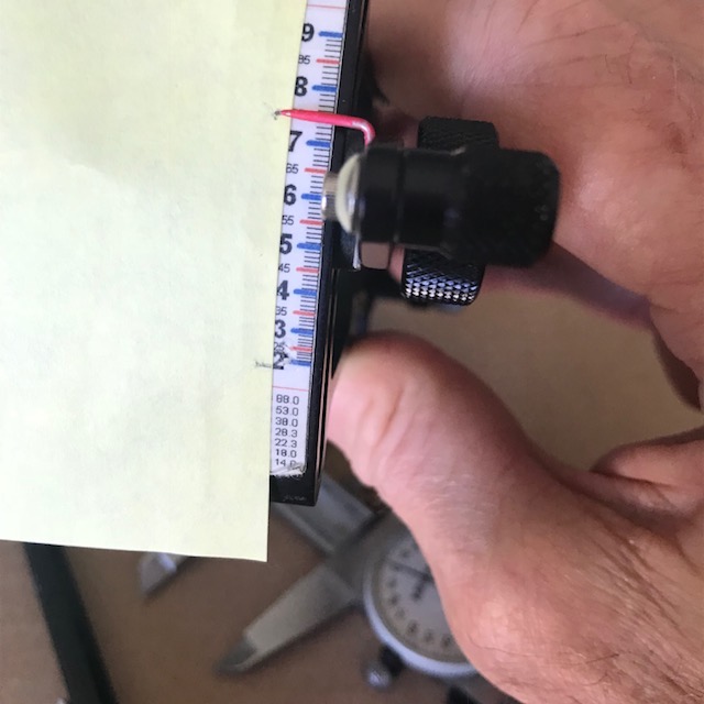
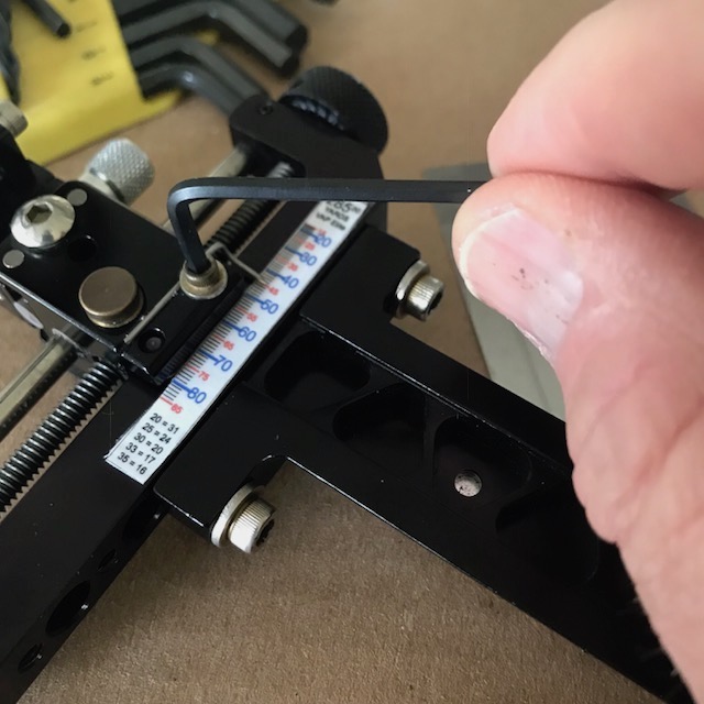
Examine the two sight scale pictures closely. What's the difference between the two scales, other than the obvious..one is laser engraved and the other is mylar? Time's up. It's the mark "thickness" that's different. The mark thickness varies from sight to sight and can even differ on the same scale. The SureLoc mylar scale has three different mark thicknesses. The "ones" marks (1 through 4..or any mark between a mark ending in a 0 or 5) are three clicks thick. The "fives" marks are five clicks thick. The "tens" marks are seven clicks thick. On the Copper John laser scale, all marks are three clicks thick. You should check your own sight to see what your manufacturer decided was the correct mark thickness.
Mylar Tape Marks
3, 5, or 7 clicks thick
Laser Engraved Marks
all 3 clicks thick
OK, so why does all this matter? If you happen to be farsighted and don't (or refuse to) use contacts or readers, think how challenging it's going to be dropping the pointer exactly at the center of a given mark. Even with good close vision, you have a 1 in 3 chance of centering your mark on the laser engraved sights. If you have the SureLoc style mylar, your chances are 1 in 3 for a ones mark, 1 in 5 for a fives mark, and 1 in 7 for a tens mark. If you like those odds, then there are lots of archers who will be happy you're content being 2 or 3 clicks "off" on a 40 yard plus target and drop some points.
Also difficult to comprehend is how you get shot in marks with the AA method? It's not like you're zeroing the vertical knob to "0 "then sliding to a known mark. When sighting in a new mark at a new distance, you don't know where you'll start or where you'll end up. You must count clicks back to a mark center, then convert the clicks to a dial number.
Initial experiencs and frustration with the AA method and a SureLoc sight, led to the development of the Mark+Click method. Ignore the numbers on the vertical knob. Slide the sight to the Mark. Jog the vertical adjust knob forward and back until the block seats in the threads. Exactly line the pointer to the Mark center, clicking as required. Click forward the +Click amount of clicks. Sighting in for a new mark at a new distance and recording a shot in mark is just as easy. Sight in, adjusting as required. Click back to the mark above the pointer; counting clicks until the pointer centers the mark. The clicks back to the mark center is your +Click count. Simple, consistent, and very repeatable.
Setting Peep Height
Generally speaking, setting your Peep Height (PH) for the archery event you're going to shoot will give better results when making a sight tape or creating marks to use. The PH that will generate the best outcome for multi-distance
events is one around the mid-point of your planned shooting distances. Easy to do and only takes a couple minutes.
Example..for field shoots you need marks from 20ft to 80yds. The average target distance is about 40yds.
So, set your scope as if you were going to make a 40yd shot...
Step 1) Close your eyes and draw the bow.
Step 2) Open your eyes.
Step 3) Is the peep aligned with the scope housing?
No? Adjust peep and repeat steps 1-3 until you open your eyes to a centered peep.
Done.
With your peep set for a comfortable hold where you make the most shots, you will have a slightly tight anchor at 20yds but your 80yd anchor will only be slightly loose. Contrast this with setting your peep height for a comfortable
hold at 20yds where every anchor will get looser the further the distance you shoot..with the 80yd almost floating.
How much float you experience will depend on sight geometry, arrow speed, where you anchor on your face.
There will be folks who are adament that they do not float their anchor, but for archers using a peep this is simply a geometric impossibility. It is NOT physically possible for your anchor to remain static when using a movable front scope and a fixed rear peep sight.
If there is no float, then something else in the 3-point anchor system must change. The change might not be much, but it is change. When you have a 3-point aiming system, all points MUST remain the same to say the anchor point does not change.
If you have a single aiming reference point, it must move vertically on the sight frame for each new distance. If you center the aim point in the Field Of View (FOV), either the peep must change position or the eye must change position for the pin to remain centered.
If your eye changed position relative to the peep to keep the pin centered in the FOV, then you either tipped your head forward or backward. If you do this and you also touch your nose to the string as a reference point, the further up the sight frame the scope moves, the more you smoosh your nose into the string. When you do this your head changes position and you've changed your anchor.
If you opened your jaw slightly to lower the knuckles and jawline anchor contact point, you've changed your anchor.
In any case, tilting your head, lowering your jaw by opening your mouth, or moving hand position to change the view through the peep sight constitutes a change in your anchor point.
If you keep your head in the exact same position and maintain the same nose to string pressure, the peep must move in order for the pin to remain centered in the FOV. If you move the scope up the sight frame, you will feel the hand contact on your face increase. This will be more noticeable if you use a handheld release and use your knuckles and jawline as an anchor reference. Less noticeable if you use a wrist release.
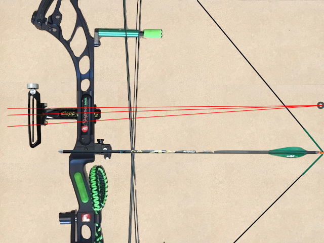
Shooting Without Peep

Shooting With Peep
Archers claiming their anchor does not change and using a peep are titling their head, moving their release hand, or changing jaw position. Tilting your head, lowering your jaw by opening your mouth, or moving hand position to change the view through the peep sight constitutes a change in your anchor point.
This is really easy to demonstrate with the help of a friend. Close your eyes and let the assistant set your sight to a random distance. Draw your bow and settle into a comfortable anchor. Open your eyes. Unless the distance is the one used to set your peep height, your peep will not be centered.
If you shoot without a peep, then your eye is the end point of the sight radius instead of the peep. If this is the case, then your anchor can remain static; but your eye will change angle and rotate to track the front pin as it changes elevation.
The only sight system using a peep as the rear sight that allows a static anchor is the Hoggernaut sight. This is because the Hoggernaught scope incorporated prisms to adjust the aim point; allowing the archer to center the peep on the scope housing without changing anchor. Sadly it is no longer in production.
Calculate Velocity From Marks
If you want the most accurate sight tapes, you MUST use the velocity from marks calculation.
SFAX can estimate the velocity from your setup, but that's just an estimate based on a manufacturer's (MFG) stated IBO. The IBO rating is a marketing tool used to sell bows. If you read the IBO "standards", you'll understand why this can be a bad idea.
A velocity from a chronograph is also just an estimate...unless the chronograph used exactly matches the one used to calibrate SFAX. In all likelihood, your chronograph will differ by up to 3% + or -. If your chronograph is off by even 1%, that's 2.8fps for a bow that shoots at 280fps.
Setup your equipment...bow (optional), arrow, and sight...by selecting them from the Database Selection tab. Each time you pick, click the Apply" button to send the data to the MySetup tab.
NOTE: when the program asks for Shaft Length, this is shaft material only...end to end of the shaft tube...no nock, no nock bushing, no point insert.
When you've finished configuring..save everything in a User Record, so you can easily reload and so you don't have to go through the data entry process each time.
For creating a sight tape the only things that are critical to get right are Peep Height (PH), Sight Radius (SR), Clicks Per Mark (CPM), Click Value (CV), and the arrow definition...and two solid shot in sight marks. PH & SR will give you the sight geometry for your ultra-close marks, the CPM & CV will give info to calculate velocity, and the arrow def will create a drag model for the calc to use.
PH and SR measurements allow the program to use the sight geometry to establish a High Pin (HP) or point blank distance for your setup. HP is defined as the distance where that pin only works at one distance. All other pins or marks will work at two distances; one ultra-close (IE: closer than the HP distance) and one far. The HP distance (usually occurs around 10-15yds or M) where, if you were to mover closer to the target, you would need to use a pin or mark for a longer distance. Your HP depends on the velocity, Peep Height, and Sight Radius of your setup.
As mentioned previously here in the Getting Started section, PH and SR must be taken at full draw and should be as accurate as you can measure. PH is center of peep to center-line of the arrow. SR is center of peep to the pin or scope lens.
Since both measurements need to be taken while the bow is at full draw, it's probably a good idea to have someone help you. You could use a draw board, but, since the draw board doesn't hold the bow the same way you do, your measurements may not be exactly the same as when you draw the bow. You must take the PH measurement with an arrow on the string, so make sure you do this in a safe place.
If you don't have a helper, an approximate measurement of PH can be made by using your front sight. To do this, set your sight as if you were going to shoot 10-15 yards/meters. Put an arrow on the string (don't draw). Measure vertically from the center line of the arrow to the center of the scope lens or aiming point. If you use a drop-away rest, make sure you take the measurement with the rest in the up position.
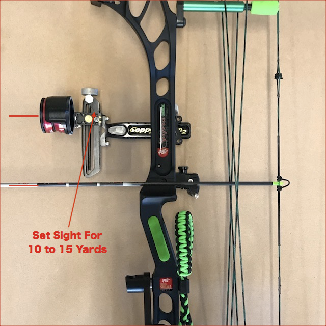
Estimate Peep Height
Estimate Sight Radius
If you know the AMO Draw Length of your bow, SR can also be estimated. True Draw Length is AMO Draw Length - 1.75". Take your True Draw Length measurement, add however many inches your sight extends beyond that point, then subtract 1/3 of the nock to peep measurement. Remember this measurement will be close but it will still be an approximation.
PH and SR values will most likely change from setup to setup, unless the bows are identical. Small changes in bow geometry and string angle will directly affect both measurements.
Keep in mind, if you guess or estimate your PH and SR, you might get a good set of marks or gaps, but what you'll get for velocity and the ultra-close distances will just be approximations. There are pictures in the Getting Started section on how to properly measure.
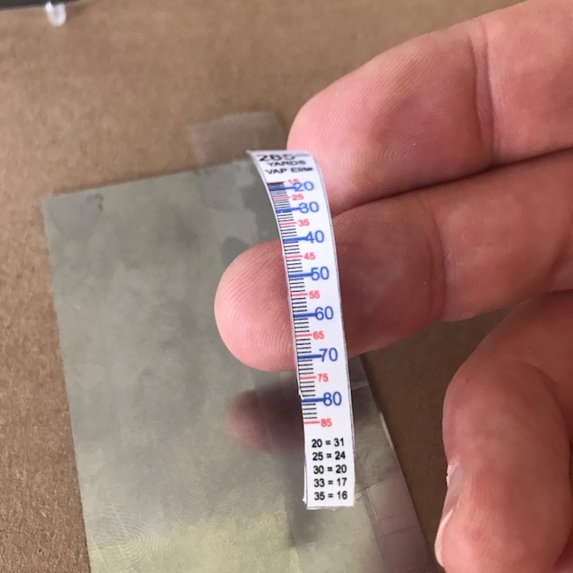
Record the sight setting from the MFG supplied sight scale as a Mark+Click(s) value. The MFG Scale is either a mylar tape or laser engraved marks, much like a ruler. Mylar tapes can be stretched when applied, so it is best to check that they reflect a true scale.
Each line on the scale is a "mark". For most sights, the distance from one mark to another is one full revolution of the vertical adjust knob. One full revolution is a certain number of clicks. For most sights there are 20 clicks from one mark to the next. On other sights there are 10 clicks and still others have 8 clicks. The number of clicks in one full revolution is your CPM number.
Most sights number the marks as a ruler would be..at the 10th mark is a 10 at the 20th mark is a 20. Shibuya does the same but drops the trailing 0..so 10 becomes 1 and 20 is 2, etc. There are still 10 marks between the numbers regardless of whether they end in a 0 or not.
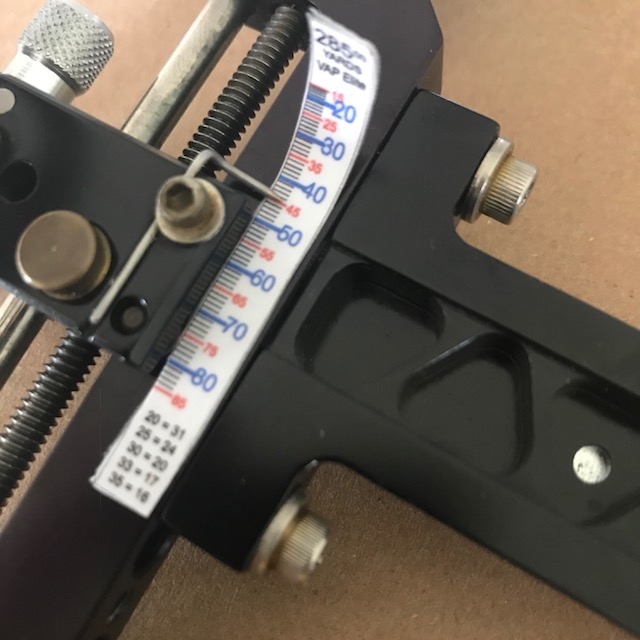
Your "mark" value is the mark less than the sight's yardage pointer for the sight in distance. Say your 30 yard sight mark is just past the "25" mark on the MFG Scale (IE between marks 25 and 26). Turn the sight's vertical adjust knob so the yardage pointer moves back to the 25 "mark" on the dial, counting the number of clicks it takes to get there. The Click(s) value is the number of clicks it took to move the pointer back to the center of the 25 "mark".
30yd Mark 25+12
Clicking Back to 25+0
Example: You turn the vertical adjustment knob and count 12 clicks to reach the 25. Your "Mark+Click" (M+C) value would be 25+12.
Click to the MySetup/Database Selections tab. Select the sight from the Sight database. Click Apply to send the sight configuration data to the Equipment tab..NOTE: you should already have done this when you built your user record.
Click to the Sight Specs tab of the MySetup view. The velocity from sight marks methods has you input the range of the sight mark in yards or meters and the M+C from the MFG Scale. Make sure to toggle the main menu Units dropdown for SAE/METRIC check mark for the range value you intend to use. Enter your 2 or 3 shot in distances and marks. Press the "Calc" calculate button to calculate a velocity. When you do this the calculated velocity is shown in the box(es) and sent to the other tabs that need it.
You can enter all the distances and marks at once and then "check" the ranges you want to calibrate. At least two rows (selected by checkbox) must be selected for calibrating. Sight Scale Marks method allows up to 3, and also allows you to cross check.
What the program is doing while calculating, is trying to find a velocity to match the trajectory of your marks and sight geometry. If your marks are "off" a little it will show up as a discrepancy in the velocity results...either plus or minus a few feet (or more) per second.
Some people use 2 marks to calibrate marks to velocity. With 3 marks, you can find marks that are off or not as good as they could be. Unless you are really confident in your 20 mark, a close mark of 25 or 30 is usually always better. You can be off multiple clicks at 20 and still hit a Vegas sized X. Your first mark is the anchor and is a reference for all you other marks in the calculations. If your first mark is "s#!+y", your resulting velocity will reflect that.
NOTE: You can use a 20 & 50, but generally, a 30 & 50 will give better results as a 20 mark is too easy to get "close enough". To see what is meant by "close enough", try changing the 20 mark you have by 2-5 clicks to see how it affects the results at distances other than your sight in marks. 2-5 clicks at 20 just moves you around a Vegas X-ring but those same 2-5 clicks have a negative impact and skew calculated velocity. But since you aren't using a 20..that's a good thing. ;-)
Using multiple shot in marks is a good way to validate marks. The "Cross Checking" feature enhances you ability to filter out "bad" marks.
Try this... Get a solid 25, 45 and 65 (or 80). Enter all three distances and the M+C values on the Sight Specs tab. For the 1st pass, uncheck the mid mark (45). Let the program calculate your velocity from the short and long mark. Running the calculation will export data to the Sight Tape and Mark Charts screens. The export will set the Mark Reference chart Sight In distance to your close sight in mark and range...and adjust the table to that M+C. Find the mid-mark in the Mark Reference table. Does the M+C agree with your mid range sight in mark? If so, you're done...print the tape or mark reference table.
If the mid-mark is off, you can fine tune by adjusting the Fletch Offset amount. If your shot-in mid-mark M+C from the Sight Specs tab distance is less than the M+C in the Mark Chart table, increase the fletch offset. Re-run the velocity calc. Click back to the Mark Chart screen and check the table for your mid-mark. You should see the table adjust until your mid mark is "on" or closer. Your short marks should also be OK at this point.
If your velocity from marks does not agree with the velocity calculated by the program from the IBO rating velocity, adjust the IBO field value either up or down until the velocity calculated from IBO agrees with the velocity calculated from your marks.
How To Make A Tape
Making a Sight Tape with SFAX is pretty straight forward. You can print to plain paper or labels. You can even use a label template but just print on a plain sheet of paper. Labels are quicker and easier, but more expensive. You can use various commercial labels. Avery 8161 work well. The program allows you to select from a list of standard sizes., so you aren't limited to just 1"x4" for size.
There's a bunch of product info at World Label...and here for the WorldLabel 1"x4" version of theAvery8161 but the label materials include different "Colors" and "Weather Proof" options. You can essentially use the label sheet until all label "locations" on the sheet have been printed to. SFAX allows you to"click" the location on the sheet where you want a label or labels to print.
Rolling your own semi weather-proof sight tape is pretty easy to do. The tools needed to make your own tape are: .scissors, Scotch brand Double sided tape, regular Scotch tape, razor blade, small rectangular thin metal putty scraper.
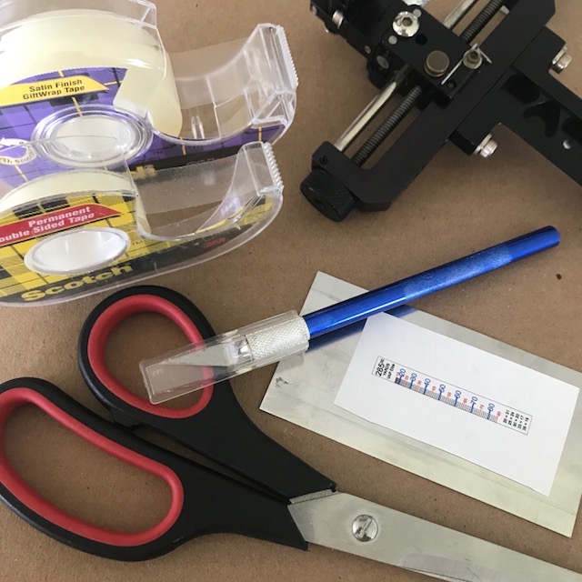
Sight Tape Kit
The way I make my tape is as follows:
Print a tape on regular printer paper and cut it out.
Take a piece of the double sided tape (longer than your sight tape cutout) and lay it along the edge of the putty scraper. One side will stick to the metal with a sticky side facing up.
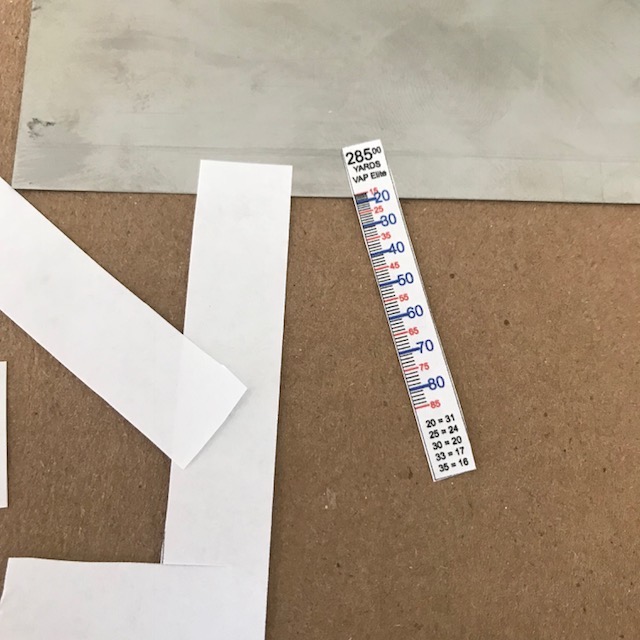
Step 1
Print and cut out the tape
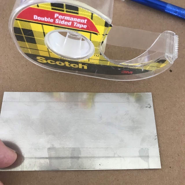
Step 2
Apply double-sided tape
Place the cut out sight tape on the sticky tape, lining up two edges of the sight tape with the edges of the scraper.
Take a piece of regular tape and place over the top of the sight tape. You now have a "tape sandwich" double sided tape, sight tape, and single sided tape.
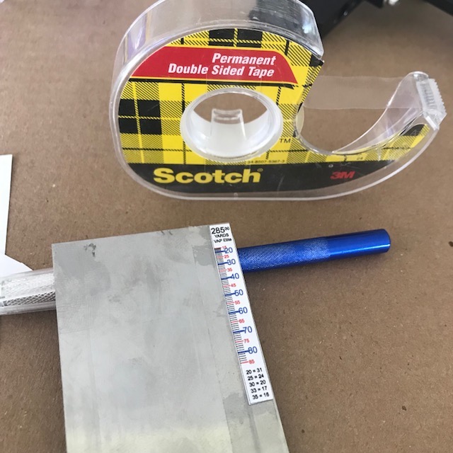
Step 3
Align the tape
Step 4
Apply single-sided tape
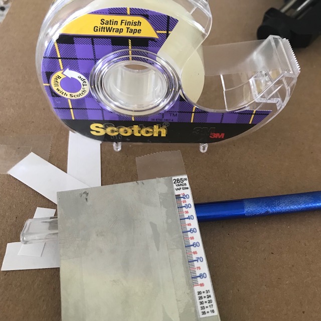
Cut around the edges of the sandwich with the razor. If you aligned the Scotch tapes and sight tape with two edges of the scraper, you'll only have to make cuts along two edges of the sight tape to free it from the scraper.
After you make the cuts around the edges of the sight tape, slip the razor between the double sided tape and the scraper and gently lift.
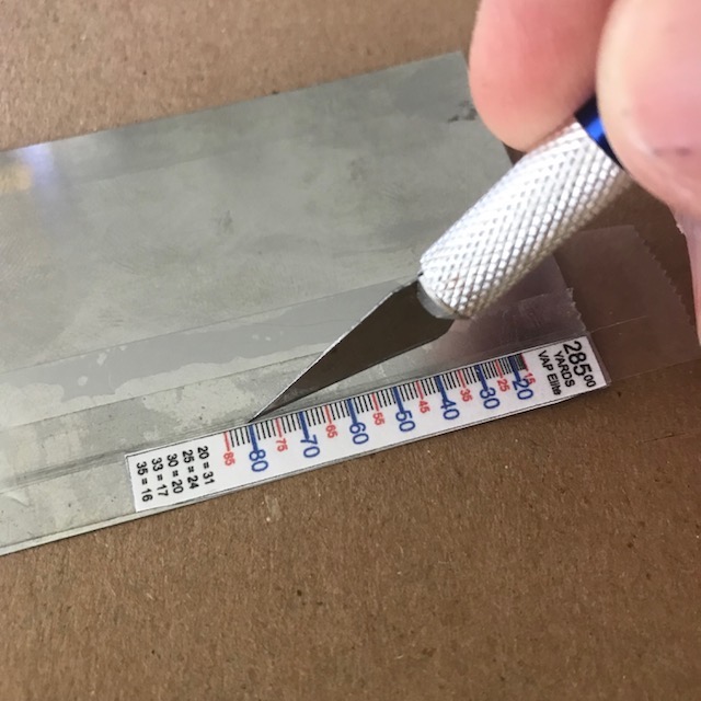
Step 5
Cut out the tape
Step 6
Apply double-sided tape
If you've done every thing correctly, the sandwich will easily peel from the scraper.
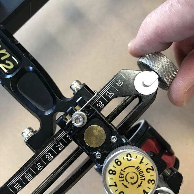
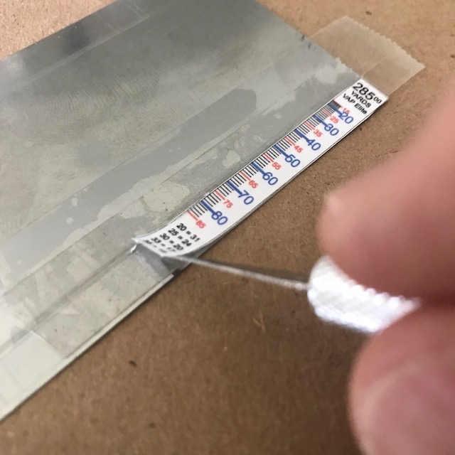
Set your sight to a known distance using your established Mark+Click setting on the Mfg Scale side of the sight. Flip the sight over and align the distance on the tape with the metal mark pointer.
Step 7
Sight tape ready to apply
Step 8
Tape aligned under pointer
Firmly press the sight tape in place.
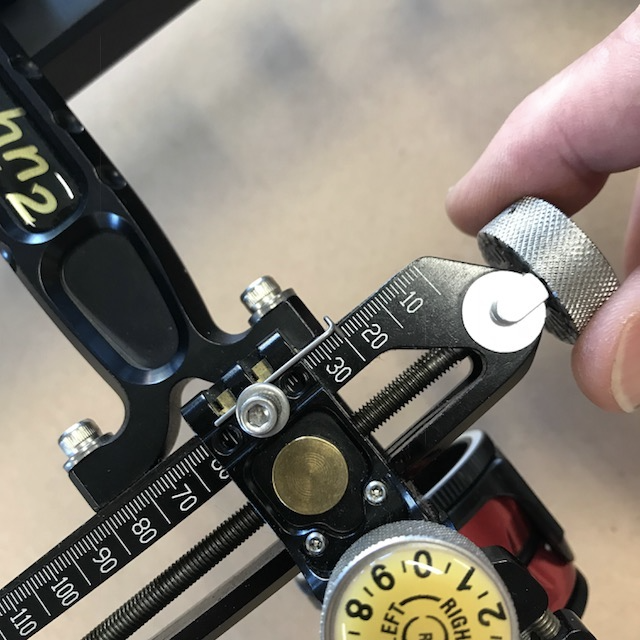
If the metal mark pointer does not exactly align with the set distance, loosen the hex screw holding the pointer and make any final fine adjsutments.
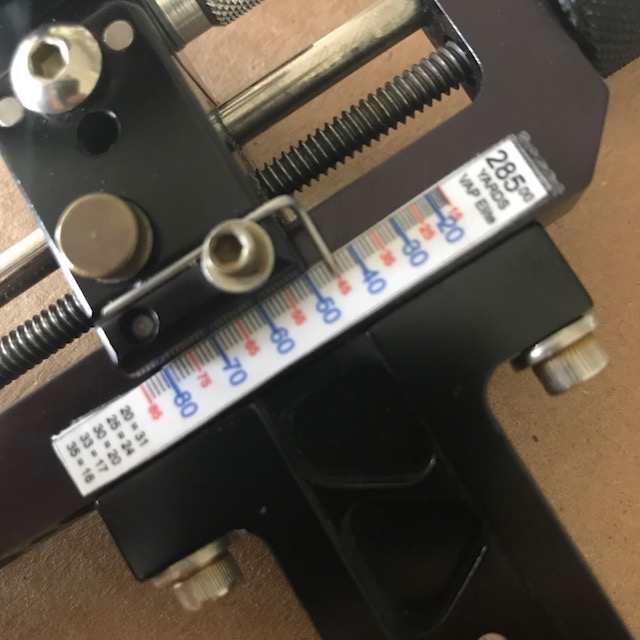
Step 9
Firmly pressed in place
Step 10
Fine adjust pointer
The purpose of the top Scotch tape layer is to seal the sandwich and make it relatively water and smudge proof. That 's it. No labels required. Just plain paper and Scotch tape.